Dave Smith Instruments Pro 2

July 14th, 2014

The Pro 2 Synthesizer is part of the new generation of keyboards from Dave Smith Instruments. Partly inspired by the classic Sequential Circuits Pro-One, and using the technology of the DSI Prophet 12, the Pro 2 is a monophonic instrument that can be a center of a synth production studio, but also has the capabilities to integrate with an analog modular synthesizer system. It’s been an honor to be asked back to the DSI sound design team to work on the Pro2. Over the course of the week of work, I archived some of the sounds to instagram and have collected the snippets here.

I couldn’t really wait to try the CV/Gate i/o features of the Pro 2, and hooked it up to the Make Noise system with triggers coming off maths. Not surprisingly, the integration is pretty tight. There are some calibration controls on the Pro 2 which had to first be adjusted, but then it was nothing but pure fun routing to and from the modular system.


The Pro2 has four oscillators and two analog filters. There’s a feature to route two of the oscillators to the Prophet 5 style low pass filter, and the other two oscillators to the Oberheim SEM style State Variable Filter. Using this routing feature, i’ve recreated a classic synth riff and sweep effect from Pink Floyd’s Dark Side of the Moon.


The Two Filter sections can run in series or parallel or mixed in-between. Series is when the oscillator is routed first to the Low Pass filter and then into the State Variable Filter, Parallel is when the oscillator output feeds equally to both filters and the outputs are mixed.


The four digital oscillators can be used as modulation sources or targets. In this patch, amplitude modulation and frequency modulation are intermixed to create tones that resemble classic Buchla tones.


The Oscillator is digital and modulating the wavetables and processing it with the digital and analog distortion sections will get you some very brash and punchy bass tones.


FM modulation of oscillators is initiated when you hit the pitch bend on this patch… that adds the growl to the screaming cat tone. Otherwise it’s just a funky filtered lead sound.


The 32 Step Sequencer is pretty powerful and with some careful programming, you can make drum loops. The Reset button on the sequencer is used as a loop retrigger while various parameters are tweaked in real-time. Unfortunately I didn’t have time to tap the full power of this feature.


The four oscillators can be split out in Paraphonic Mode. You can play four different notes on the keyboard but all four voices share the filter bank section. A bouncy part like this New Order riff sounds like it’s coming from a true polysynth.


Most people would expect the Van Halen, Jump synth riff… sorry to disappoint. After a week of non stop patch programming the brain does weird things…


The internal feedback routing from the Prophet 12 is also available in the Pro 2. Along with some non-standard key tracking modulation and synced filter effects rendered this IDM fill sound.


Gotta Have More Cowbell! This patch uses the Roland TR-808 approach of specifically tuned pulse waves to create the ringing effect.


In this video, the Pro 2 sequencer is sending CV/Gate signals to the Moog Werkstatt. The Audio from the Werkstatt is routed back to the Pro 2 audio input and processed with the bit crusher effect and filters.


The Pro 2 Sequencer tracks can be routed to four different CV out sockets. Here the minimoog model D is being triggered and sequenced by the Pro 2. Users of Propellerhead Thor Polysonic Synthesizer will notice that the modulation matrix looks very familiar!

Moog Werkstatt-Ø1

June 20th, 2014

The Werkstatt-Ø1 is a monophonic analog synthesizer with with a single VCO, resonant low pass ladder filter, LFO, envelope generator, one octave keyboard, and mini patch bay. Using jumper wires, you can experiment with different patch routings. While it’s a fun unit on it’s own, the circuit board has a section designed specifically for experimenting, and clear points that allow you to make modifications.

The Werkstatt was introduced at Moogfest 2014 as part of a special engineering workshop in the Moog factory, and I was quite fortunate to be among the first group to build this synthesizer. We were provided the tools to solder in a few dozen components (approximately 200 solder joints) to a partially populated circuit board. Under the guidance of Werkstatt designer, Steve Dunnington, and the Moog engineering staff, all of us had our new synths up and running by the end of the first day!


I borrowed this TT-303 Bass Bot (TB-303 Clone) to take to Asheville. Like the TB-303, the TT has CV/Gate outputs. I was hoping to punch some holes and add 3.5mm jacks during the workshop, but had to settle on making a couple patch cords. The TT-303 CV out is connected to the Werkstatt VCO, and the 303 Gate out is connected to the Werkstatt VCA.

Werkstatt as a Synth Module

The Werkstatt design is ‘somewhat’ influenced by the Eurorack modular format. It has a height of 3U, so it has the same vertical dimension of a Eurorack module. It runs off a 12V DC supply voltage, and so it can be powered from a Eurorack supply. Despite these commonalities, it would be difficult to convert the Werkstatt to a Eurorack module without considerable hacking. The 1/4” audio output jack and the power connector jack are situated right on the edge of the PCB, which is already too large to fit between Euro mounting rails. If someone were to fit this in modular case, they would have to customize the space to accommodate the entire box.

The Werkstatt has the potential to complement a modular rig, but the header patch bay lacks a common grounding point, making direct connections with outside gear a little more difficult. For basic routing, I’ve made jumper cables that have a 3.5mm plug and terminate with a patch pin. Grounding is achieved by routing the Werkstatt audio output to a mixer/vca module in Eurorack system (1/4” to 3.5mm mono patch cord). This is probably the easiest (and least destructive) way to interface the Werkstatt with modular gear.

In this photo, the TB-303 CV/Gate outputs are patched to the Werkstatt VCO EXT In and VCA In using the 3.5mm to single pin patch cables. Common ground between the 303 and the Werkstatt is established by connecting the audio to the 303 Mix input. This is important because if there’s no ground reference, the CV/Gate signals will not control the Werkstatt.

The kit includes a few patch jumpers (3M - part number 924962). You can find other brands of leads designed for arduino experimenter kits that connect into 0.025” headers. I found these jumpers by Osepp, (part number LS-MMPJ-6) and soldered the ends to a mono patch cord. The joint is a little delicate, so it’s important to use some shrink tubing to insulate and reinforce the connection.

VCO CV Calibration


On the patching header, there is an input called “VCO EXP In” which is the oscillator pitch control that can be modulated from a step sequencer. The Werkstatt follows the tuning convention of 1 volt per octave, and will interface with Eurorack sequencers. If you are using a module that outputs quantized voltage values like the Make Noise Rene, this input may require calibration.

The VCO EXP TRIM knob is VR5, located right below the “moog” logo on the circuit board. Basically you send 1 Volt DC values into the VCO EXP In pin, and adjust the VR5 using a small screwdriver until you hear octave divisions playing from the Werkstatt. Adjusting this control will not affect the keyboard tuning, only incoming pitch cv scaling. We were told that Bob Moog always used a frequency counter to calibrate synths, but you can adjust it manually by using another oscillator as a reference. Once the VCO EXP TRIM adjustment is accurately calibrated, the Werkstatt should track perfectly with a CV keyboard or sequencer.

Attenuator

Using a 500k potentiometer and a couple of jumper leads, a simple attenuator can be incorporated between routings. You can patch the VCO into the VCF and control the intensity of the cutoff frequency modulation. 500k is just enough resistance to scale the keyboard control voltage to the LFO, and this allows you to have two tuned oscillators by patching the LFO out to the Audio input.

With a little extra work, you can mount the potentiometer in an enclosure, and then add your favorite style of knob! In the photo below, i’ve mounted the potentiometer (alpha part RV16AF-10-15R1-B500K) in a Bud Industries, die cast enclosure (part CU-123) with a Davies knob.

Modding the Werkstatt

Most of us who built the Moogfest Werkstatts have contemplated whether or not to apply drastic modifications to these units. They are are the first batch to come out of the factory which already has a special significance, and it would be a shame to butcher the unit. Lately I’ve been tossing around the thought “What would Bob Moog do?” And the answer i keep coming up with is that Bob would probably mod it :-) Below are a few modification ideas. Some are original and others are ideas passed on from Steve Dunnington during the Moogfest workshop.

White Keys


The easiest mod is changing out the keyboard buttons and replacing the whole note keys with white button caps. The added contrast makes it easier to find your position along the scale and gives it an overall cooler look. The tact switch key caps come in a range of colors and are available from the major online electronic component suppliers. I’m using the Mountain Switch 101-0209-EV. Be careful when removing the old key caps so that you don’t break a solder joint. They should pop off by hand without too much effort.

Envelope Trigger Input

One mod that I’ve been obsessing over is an Envelope Trigger input. While you can apply an external envelope signal to the VCA or VCF input patch points, there is no way to actually trigger the envelope except through the note buttons.

I’ve been experimenting with various ways of tapping into the circuit. The envelope generator has two modes: Pulsed and Sustained. When a key is pressed, both a sustained gate and 5ms trigger are generated and sent to a selector switch (SW8). From the switch either the pulse or sustained gate signal passes to the slew circuit. So far using a voltage follower has been the most reliable and way of applying external gates into the envelope. This will ultimately be added to the experimenter section of the circuit board, and it will be necessary to cut a trace to insert this connection.

I’ve breadboarded a voltage follower and patched it into a solder trace on the Werkstatt. An external gate from an XAOC Moskwa sequencer (which can be finicky) runs through the voltage follower and into the envelope generator.

Distortion

One of the mods suggested in the workshop was adding a diode clipping circuit between the filter and VCA. There’s a jumper on the board where you can insert a passive (or active) distortion circuit for a little extra character. Using a few spare parts I managed to get a nice diode clipping circuit going. It’s a nice mod, but i’m not sure i would always want it active, so part of this plan is to add a switch that will bypass the distortion.

In this photo, the Make Noise Rene is sequencing the Werkstatt. The gate from Rene goes through the voltage follower circuit (on the breadboard) and triggers the envelope generator. The distortion effect is also wired in on the jumper between the VCF and VCA.

Audio Input

The Werkstatt PC Board has a jumper connection that links the output of the oscillator to the filter section, providing an access point to run a signal though the filter alone. You can still modulate the cutoff frequency with the LFO or apply some FM modulation by patching the oscillator to the filter cutoff, and run another audio source like a drum machine or external module though the moog filter. During the Moogfest workshop, Steve Dunnington showed us a prototype mod he applied with an audio input buffer that taps into this point. This mod, however, is destructive and requires the addition of some circuitry and a switching input jack, or a separate switch that disables the oscillator.

3.5mm Jack Panel

Drilling holes into the Werkstatt is ultimately going to be the most daunting task. Having little skill as a machinist, there’s the distinct possibility of messing this up. As a measure of precaution, I’ve decided to have an aluminum panel made by Front Panel Express with the holes precut. Not only will this look neat with clearly engraved labels, it leaves a little room for drilling errors into the Werkstatt itself. There isn’t a lot of vertical clearance between the PCB and the bottom of the case, but as long as the holes are centered along the axis of the existing power and audio jacks (approximately 9.1mm from the bottom of the case), a typical Kobiconn 3.5mm jack will fit (sideways) with a just enough of the bushing to fasten it down.

Since the experimenters pads will be used for the gate buffer and distortion circuits, so I’ve avoided populating that section with jacks. Some of the components may have to be mounted under the PC board, and so the extra clearance is required. The mechanical engineering is something that takes me a little extra time, primarily because I’ve been prone to really dumb mistakes. When completed, I will be able to patch the to and from a modular rig with ease; essentially making the Werkstatt a stand alone module. Hopefully, this will all work out.

Robotspeak Workshops

Robotspeak in San Francisco is a dealer for the new batch of Moog Werkstatt Kits, and I’m going to organize a day or two to talk about using it with other analog gear, build patch jumpers, and work on some of the mods described above. Yes, including the custom patch panel.

A little modular music

June 12th, 2014

idea sketch ES 14.59 from Kurt Kurasaki on Vimeo.

I’ve been creating and archiving quite a few of these little modular pieces for the last year. This is one of the latest patches that utilizes modules from Make Noise, Verbos Electronics, Livewire, and Music Thing / Thonk. The patch is fairly pre-set, relying on a couple of base sequences that are scanned at random rates based on values generated by the Livewire Chaos computer. The oscillators are inter modulating to dynamically change timbre, and one sequence also drives the minimoog model D that provides the backing pad. Most of the build up and breakdown is manual tweaking of dynamic and timbral controls for a sense of live performance, but the notes and sequence themselves are random.

Bad Power Cable - Almost Destroys Gear

April 18th, 2014

This is yet another one of the various nightmares one can encounter when dealing with audio hardware. While patching my Eurorack modular rig into a tube mic pre, I felt the light buzz of an electric current passing through my fingers. Obviously, this is not a good sign, and it means something is terribly wrong. After disconnecting everything except power, I tested for voltages across grounds and discovered a 120V AC difference between the tube amp ground and the Eurorack case. As it turns out, the problem was the IEC power cable… yes, that unassuming three conductor cord that connects to the power main was at fault!

A continuity test revealed that this cord is essentially cross wired. This means the Neutral from the mains is connected to the Load of the IEC connector and the Load (Live wire) from the mains is connected to the Neutral. In the photo above, you can see continuity between the Load contact and the Neutral on the IEC connector. Even with the synth switched off, power was running into the system, and a bit of current was finding it’s way to the panels and case.

Unfortunately, I have no idea how this cable was acquired. It was just in the box of power cords, and presumably correctly assembled (how the heck can you mess up 3 connections?) The cord is labeled, “PVC YOUZHI DIANXIAN 3C RVV 300/300V,” and it’s missing the country of origin. A quick websearch reveals that it was manufactured in China, and YOUZHI DIANXIAN is known for other substandard cable products.

The good news is that the synth and tube amp are fine, but i ran into problems with some other audio gear. A few components are blown (again) in my monitor control system, and I need to check on some vintage compressors. I’m just lucky that it didn’t cause more severe problems like data loss or death :-/

Cable has been properly destroyed, and is ready for recycling! Moral of the story: always use the IEC cable supplied with the gear or test the contacts to make sure they are not crossed before you connect to the mains.

Cassette Recording Audio Processor Rack Extension

April 1st, 2014

The Cassette Recorder Audio Processor Rack Extension is an analog emulation effect for the Reason Rack that will enhance your audio with the smoothness and colour unique to analog recording. Yes, CRAPRE adds the warming sound of ground loops and tape hiss while enhancing incoming signals with harmonic destroytion! Our crap staff of mad nerdbags has discovered a special undocumented feature of the Rack Extension SDK: a colorful user interface with pink knobs, kittens, rainbows, and unicorns optimizes CPU usage while psychedelically extending the digital music stuff from 32 bit to a whopping 41 bit super-endian-rainbow-floatiger maths! In laymen’s terms, this means Crapre sounds terribly good! The wow and flutter algaerytm adds a deluxe warmingness, and it even simulates “tape eating” for hi definition low fidelity realistic results!

LEARN MORE - CLICK HERE!

Tesla Coil Samples

February 27th, 2014

For those who follow my social media streams, you may have already seen the various DIYAudio, DIYSynth, DIYrepair projects going on around here for the past year. One of these projects is the oneTesla Musical Tesla Coil kit. In “synth speak” it’s essentially a pulse wave oscillator. The oneTesla incorporates an arduino brain that receives MIDI note information, and the sparking plasma threads emitting from the coil oscillate at musical pitches. I certainly recommend the kit if you’re looking for a fun weekend project, however it may require some debugging and may also require the need for a function generator and oscilloscope. Over the past year it seems that the development team has ironed out the kinks in the design and even novices generally have great success in their builds.

The link below is an archive of the multisampled notes generated from the oneTesla. I’ve provided the archive as a folder containing an NN-XT patch. The audio was recorded at quite a distance from the Tesla coil, mainly because I didn’t want the coil to discharge through the microphone, but also because the output is incredibly loud. The recorded results aren’t as impressive as having the real-time audio-visual experience, so get a better “feel” of the actual sound, it’s recommended that you run the sampler output into a peak limiter and push the gain up 3dB to 9dB, and play the samples back at very high levels. The coil is sampled note-by-note from MIDI C0 to C5, and you will hear “spark” artifacts and a few obvious loop edits.

oneTesla-TeslaCoil_samples.zip

Alias8 CV Modular Patch Challenge!

February 24th, 2014

Thanks to all those who participated. We now have a winner!

Modular Patch Challenge

Alias8 CV Controller Rack Extension

January 8th, 2014

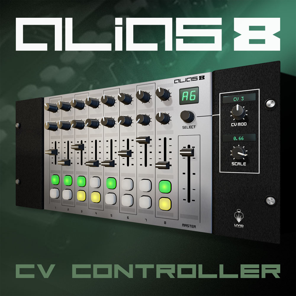
The Alias8 Rack Extension is all about control. Place the device at the top of your rack, route some connections, customize the labels, and start tweaking. Once your routings are configured, you no longer have to scroll through to find that all important filter knob or trigger button in your complex rack setup.

The Livid Instruments Alias8 inspired the idea of having a Reason Rack Extension that visually mimics a hardware control surface and seamlessly integrates remote mapping; bridging the gap between you and the Reason rack. This collaborative effort with the good people of Livid Instruments has resulted in the ultimate virtual control interface, the Alias8 CV Controller!

Available from the Propellerhead Shop

Example Reason Files

Loop Launch and Live FX: Alias8-REXandFX.reason.zip
Alias8 Modular Style Song Demo: Alias8-stockdevicedemo.reason.zip
Granular Sample Manipulator with Buffre Beat Repeater: Alias8-BuffreConcrete.reason.zip

Operation Manual

Detailed Documentation which includes various example projects is available from the following link:

Alias8 CV Controller Operation Manual

Version 1.0.1 PDF Download. Requires Adobe Acrobat or other PDF Reader

Livid Instruments Alias8 Hardware Controller

The Alias8 Rack Extension works seamlessly with the Alias8 Hardware controller through Reason Remote scripting. There’s some basic setup required as well as a recommended firmware upgrade. For more information, please visit the Livid Instruments Reason Support Page

For more information about the Alias8 Hardware Controller, visit the Livid Instruments Website

Korg MS-10 Ressurection

August 29th, 2013

Last winter, my friends, Ryan and Lisa came for a visit and brought along a Roland TR-606 and a Korg MS-10, both of which were not working.  The 606 was easy to fix since the lead to the battery compartment had come loose.  The MS-10, however, was a completely different story and required a lot more research since I’ve never undertaken a repair like this before.   I’ve managed to get the MS-10 back up and running, and I want to share some of this information, just in case someone out there runs into a similar situation.

The Korg MS-10 was purchased in Europe but came with an unpolarized NEMA AC connector that looks like it would work in Japan or North America.  When Lisa and Ryan used this in Europe, they had it connected to a power adapter which bucked the voltage down from 220V.  After moving to the US, they (Ryan) plugged it into a regular 120v socket, and it started smoking.  Since then it has been dead.  Whenever I would visit their home, i would see the dead little MS-10 sitting as a bit of decoration on a table.  

About a month ago, this project seemed like it was ready to be tackled.  Fortunately, the service manual is available from several sources online.  Synthfool is not only a great synth tech, but provides the community with the archive of these materials.  After studying the schematics I started to open up the unit and noticed something odd.  The badge says it’s requires 15 volts ac.  This was a head scratcher, and I thought perhaps it was a misprint and should have been stamped 115 rather than 15.  It simply makes no sense especially since it has a NEMA plug.  


So after opening up the unit, I discovered that the transformer is basically used as a coil.  The incoming voltage from the AC line runs into one leg of the primary then passes through the other leg of the primary right into the motherboard.  The other leg of the AC line passes into a fuse (which was blown) and the power switch then into the motherboard.  I was expecting to find a normal AC connection where the incoming power connects through the fuse and switch to the primary of the transformer, and the secondary windings of the transformer passing to the motherboard.  However the way this was wired, the badge was indeed correct, and it was intended to run off of a 15 VAC power source… not 220/240 or 110/120vac.  When the MS-10 was plugged into a socket, 120 volts was sent straight into the motherboard and did some serious damage.  

At first, i thought maybe I can get lucky and just replace the rectifier diodes and the 7815 and 7915 voltage regulators and it will be done.  I pulled the diodes and regulators and found that the diodes were OK, but the regulators were shot.  Fortunately a these components are easy to get, so I popped in the new ones and started to see some signs of life.  The LFO light started blinking, and I could hear some noise.  The keys wouldn’t play, but after patching the LFO into the VCA, I could hear some activity and I could adjust the filter into self-oscillation.  While far from being perfect, there were some signs of life, and I figured, why not push forward to see how far I could get.


According to the schematic, the MS-10 oscillator section takes power right off the transformer… however in this case, 120VAC was injected into this part of the circuit.  This would be good place to start looking.  Sure enough some of these FETs were damaged and replacing them got a 60Hz hum being shaped into a sawtooth and pulse, however the envelope generator and keyboard were still not working.  It dawned on me that half the AC leg might have still been active after the fuse blew, so there was still a lot of voltage passing through the circuits and to ground through the audio out socket.  It made perfect sense that the CMOS components were damaged and many of the op-amps (TL0s, etc).   After replacing many of these more sections started to function.  The envelope generator, the modulation routings, etc.  Sure enough, after replacing all of these components everything came back to life!

Thinking that a critical component might have been damaged, i also sourced a special NPN transistor pair (2SC1583) at the heart of the oscillator.  This part is also used in the TB-303 and x0xb0x and has become rather difficult to find.  To make matters worse, according to a thread on the adafruit forum, counterfeit versions are floating about, so i avoided the foreign eBay suppliers.  As it turns out, the original transistor was not damaged.  I popped in the new transistor, and I was surprised that there was a bit of a difference in sound.  The original transistor has a bit more character and bite, so i put it back in.  I’ll keep the spare in case one of my old synths needs work.


I thought about properly wiring the transformer back into the circuit, but instead opted to leave the power section untouched.  This particular MS-10 still runs off 15 volts AC, but the original power cord has been removed and replaced with a 2.1mm power jack and a wall wart.  Hopefully this mistake will not be made again in the future.   The moral of the story is this:  Yes, apparently Korg made some MS-10s and MS-20s that were designed to work on 15VAC, but have a North America AC plug.  If you plug one of these 15V units into a 100/110/120 socket, it will definitely fry.  If you’re in Europe and plug it into a 220/240 to 120 converter, it will fry.  

I tracked some raw samples of the unit.  You can download the Reason session here:
KorgMS-10rawsamples.reason.zip

and a short video:

Reason CV Tutorial Series

July 10th, 2013

As the Reason ecosystem continues to grow with many unique control voltage rack extensions, it seems important to provide new users with a means of learning CV routing. To get things started, I’ve put together some basic tutorials. These are based on some past works and updated for Reason 7. This is a continuing series, and new tutorials will be added regularly. The lessons are embedded in the rack on Spacre panels adjacent to example device configurations, allowing for a hands-on experience for learning about each topic presented.

Reason Control Voltage Tutorial Page

Buffre / Spacre Bundle

July 8th, 2013

Purchase Buffre Beat Repeater and get Spacre Blank Plate as a free add-on to your Reason Rack Extension inventory. Details on the Buffre/Spacre Bundle page in the Propellerhead Shop.

Directre Audio Router

March 4th, 2013

DIRECTRE is an audio routing utility designed to work as a hub for a live performance using Propellerhead Reason. Directre’s audio switching synchronizes to the tempo of a song. With a press of a button, a channel switch is cued to open or close at the beginning of a measure, beat, or 1/8th note. DIRECTRE can function as either a 1×8 splitter device or as an 8×1 summing bus. In addition to the quantized switch capabilities, the switch can be adjusted to fade in and fade out with a touch of a button.

Directre Information Page